Real experience from David how to design dummy battery module and heating film, both thermodynamics and structure need to be considered.
There has been an introduction to the structure of the dummy battery before, and the key components of the dummy module and heating film design scheme are introduced below. Both thermodynamics and structure need to be considered. This time, the cold plate of the Dummy battery was tested with refrigerant R134a.
One thing needs to be clarified. The battery pack is composed of modules, for example, 8 modules form a battery pack. The module is composed of cells. For example, 24 cells form a module. If the module batteries are connected in series, then the module can be described as 1P24S, and the whole package can be described as 1P192S. If the nominal voltage of the single cell is 3.4V, the nominal voltage of the whole battery pack is 652.8V.
Figure 1 is an exploded view of the battery system, you can clearly see the relationship between the battery pack and the module.

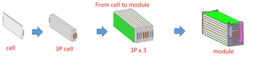
Figure 2 is the assembly sequence diagram of the battery cell and the module, you can clearly see the relationship between the battery cell and the module.
The following briefly describes the technical terms of the power battery pack, which can give you some intuitive understanding. As shown in Table 1 below.
Table1 Definitions of terms and abbreviations
| Battery Cell | The smallest energy storage unit, a basic electrochemical energy storage device, consists of a positive electrode, a negative electrode, an electrolyte, a separator, an exhaust valve and a shell, and is also called a cell. |
| Battery Module | The intermediate energy storage unit, placed in a mechanical and electrical unit, is a combination of several units connected by the circuit and circuit equipment (monitoring and protection circuits, electrical and communication interfaces), also called a module. |
| Battery Pack | A power system composed of several battery modules, circuit equipment (protection circuits, battery management systems, electrical and communication interfaces), and thermal management devices to provide energy for electrical devices. |
| Nominal Voltage | Indicates or identifies the approximate value of the appropriate voltage of the battery. |
| Capacity | The amount of power that the battery can provide after being fully charged under the specified conditions. Usually expressed in Ah. |
| Energy Capacity | The energy that a battery can provide after being fully charged under the specified conditions. It is usually expressed in Wh or kWh. |
| Nominal Capacity | At the beginning of life (BOL), the battery fully charged under the specified conditions can provide the minimum capacity that can be discharged at a rate of 1/3C (C-rate).Or at 1C, this depend on OEM. |
| DOD | The ratio of discharge capacity to nominal capacity. |
| C Rate | The current value of a fully charged battery with 100% SOC when it is discharged to 0% SOC in 1 hour is A; C rate is defined as the ratio of a certain constant current value of charge and discharge to A; For example: 1C refers to the current when a fully charged battery with 100% SOC is discharged to 0% SOC in 1 hour; 0.2C refers to the current when a fully charged battery with 100% SOC is discharged to 0% SOC in 5 hours. |
| Self-Discharge | A phenomenon in which the usable capacity is automatically reduced due to spontaneous or undesired chemical reactions inside the battery. Monthly self-discharge rate usually refers to the rate of reduction of available capacity in the current month. |
| SOC | The ratio of the remaining power to the nominal capacity. The standard value is 0%-100%; 0% means that the battery is fully discharged; 100% means that the battery is fully charged. |
| SOH | The remaining service life is the ratio of the nominal service life. The standard value ranges from 0%-100%; 100% refers to BOL. |
1.Real battery cell data sheet
| Nb.1# | Items | parameter | unit |
| 1 | cell dimension | 14*123*80 | mm |
| 2 | Mass of cell | 0.3 | Kg |
| 3 | Density of cell | 0.0025 | g/mm-3 |
| 4 | specific heat capacity of cell | 980 | J/kg.K |
| 5 | cell quantity per module | 1P24S | pcs |
| 6 | cell quantity per pack | 1P96S | pcs |
In addition, according to the DCIR and SOC-OCV of the cell, the heat generation value of the cell under different working conditions is calculated. In addition, you need to pay special attention to the heat capacity of the cell itself. For example, the above-mentioned cell needs to drop from 35°C to 25°C in 30 minutes. In addition to heat generation under working conditions, the heat capacity of the cell itself needs to be taken into consideration. 201830.4J, the power is 112w, as shown in the figure below.

the above-mentioned cell needs to drop from 40°C to 32°C in 10 minutes, in addition to heat generation under working conditions, the cell’s own heat capacity needs to take away 161644.32J, and the power is 269w, as shown in the figure below.

2.Dummy battery module thermal capacity design consideration
The design of the dummy battery needs to be consistent with the size of the real battery, especially the external dimensions, cooling contact area, and installation dimensions. In addition, from the perspective of thermodynamics, due to the use of aluminum alloy for the dummy battery, the specific heat capacity of the aluminum alloy is 880J/kg.K, which is smaller than the real battery, so the weight of the dummy battery needs to be 1.11 times heavier than the real battery to heat the two Content is equal. It is necessary to establish the digital model of the module in a three-dimensional modeling software such as Catia, and give the density information of the aluminum alloy to calculate the weight of the module to optimize the design.
As shown in the battery module in the figure 3 below, the black area is the battery heat dissipation area.

As shown in Figure 4 below, the designed dummy module needs to be the same size and shape as the real battery module(figure 3), especially the heat dissipation area.


3.Realization of Dummy battery heat generation function
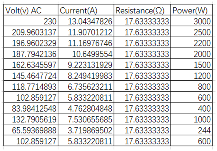
The heating film is used to heat the dummy battery, and the power of the heating film is designed according to the heat produced by the real battery. The resistance of the heating film is designed to be 17.63Ω, and the power of the heating film can be changed by changing the input voltage of the heating film. The voltage corresponding to the theoretical design output power is as follows. Below table for your reference.
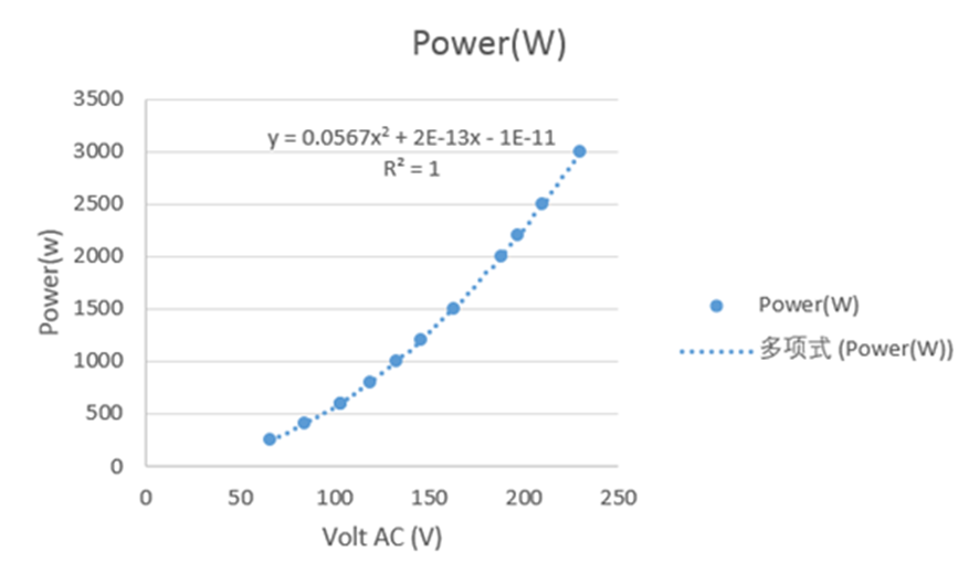
By fitting the curve of voltage and power, the input voltage can be adjusted manually or automatically to reach the target heating power.
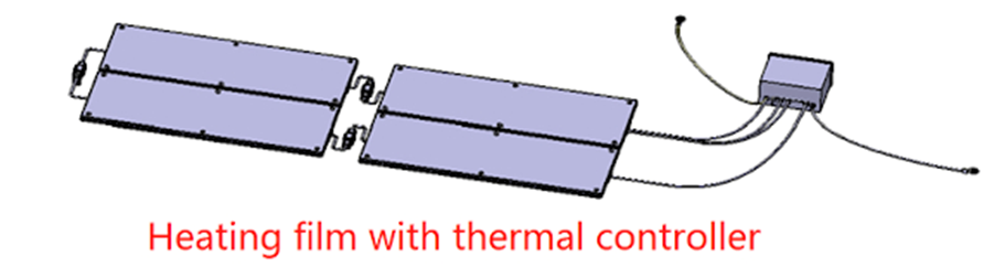
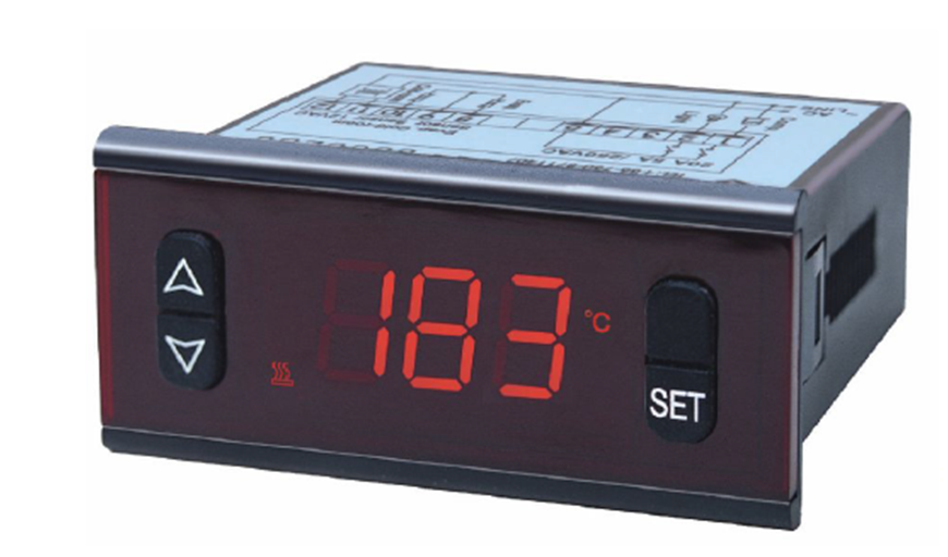
After the power design goal of heating film is achieved, Catia can be used to design drawings and use silica gel heating film. In order to ensure the safety of heating, the heating film is equipped with a digital display temperature controller. When the detected temperature is greater than a set value, the power supply is disconnected.
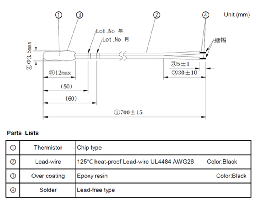
NTC probe adopts Hoverbird, model: ED2I103C0-14C006. The specifications are as follows:

NTC needs to operate reliably at -40~125℃. The size of NTC is shown in the figure below. Of course, the size of NTC drawing 700mm can be changed according to the actual application.
4.SUM for the dummy battery design
The above dummy and heating film are the key parts of dummy Kit and represent the battery cell of the power battery module. After the design drawing of a single module is determined, it can be processed according to the actual number of modules in the pack, normally the dummy battery module is CNC machining acc to drawing. Other parts such as bolts, thermal pads, lower shells, etc. are designed and processed according to the previously introduced documents. Since then, a dummy battery kit has completed the thermodynamic and structural design and can be processed.
If you need to discuss something, email david for more, his email is: david.teng.fiter@gmail.com